|
9.2 -
|
|
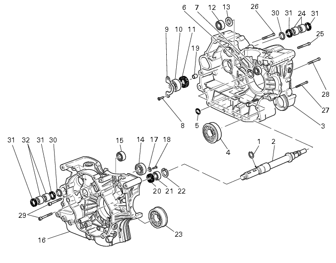
1
|
|
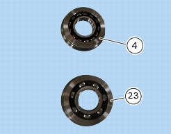
4
|
|
5
|
|
6
|
|
7
|
|
8
|
|
10
|
|
11
|
|
12
|
|
13
|
|
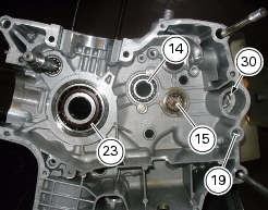
14
|
|
15
|
|
17
|
|
18
|
|
19
|
|
20
|
|
21
|
|
22
|
|
23
|
|
25
|
|
26
|
|
27
|
|
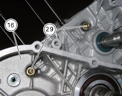
29
|
|
30
|
|
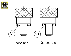
31
|
|
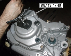
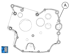
Remove the complete head unit with timing system
|
|
|
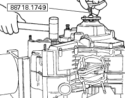
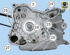
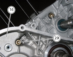
Remove the generator-side cover and the complete generator
|
|


|
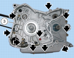
-
|


|
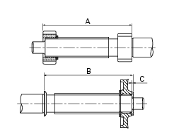
M8x75 mm screws
|
||
|
M8x75 mm drilled screw
|
||
|
M6x35 mm screws
|
||
|
Refit the generator-side cover and the complete generator
|
|
|
Refit the complete cylinder / piston assembly
|
|
|
Refit complete head assembly and timing system parts
|
|