|
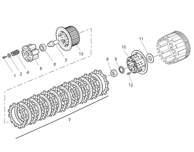
1
|
|
2
|
|
6
|
|
8
|
|
10
|
|
11
|
|
12
|
|
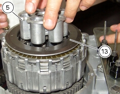
13
|