|
9.2 -
|
|
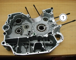
1
|
|
2
|
|
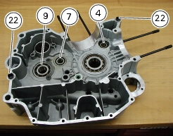
4
|
|
5
|
|
6
|
|
7
|
|
8
|
|
9
|
|
10
|
|
11
|
|
14
|
|
15
|
|
16
|
|
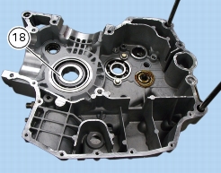
18
|
|
19
|
|
20
|
|
21
|
|
22
|
|
23
|
|
25
|
|
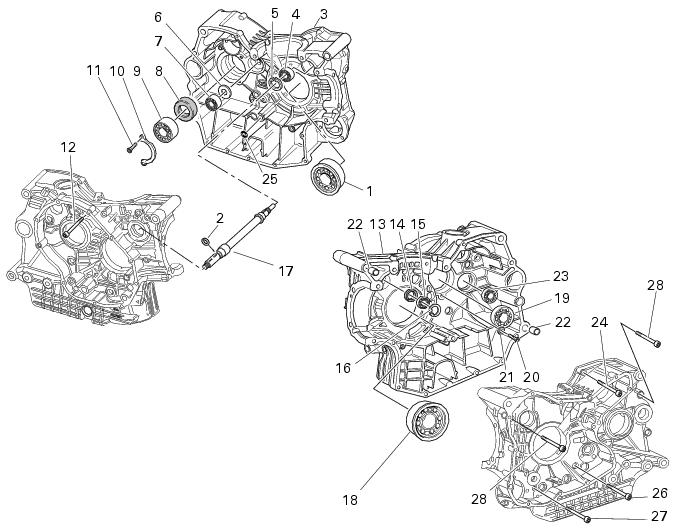
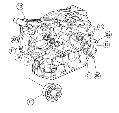
Remove the complete head unit with timing system
|
|
|
Remove the generator-side cover and the complete generator
|
|


|
-
|
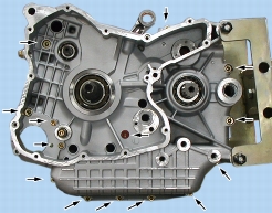
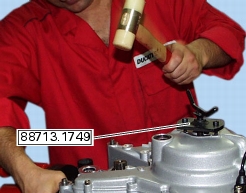
heat the casing in an oven up to 100 °C.
|
|
-
|


|
Refit the generator-side cover and the complete generator
|
|
|
Refit the complete cylinder / piston assembly
|
|
|
Refit complete head assembly and timing system parts
|
|