4 -
Maintenance operations
Checking the engine oil level
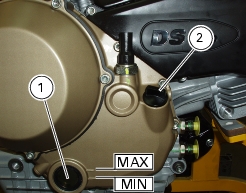
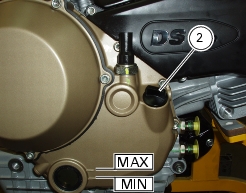
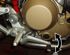
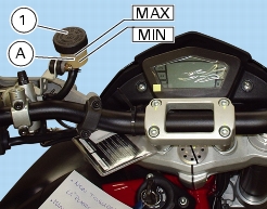
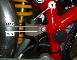
Check the engine oil level in the sight glass (1) on the RH side of the oil sump.
After switching off, allow several minutes for the oil to settle before checking the level. Check the level with the motorcycle
perfectly vertical and with the engine hot (but stopped).
Level shall be between the MIN. and MAX. notches. If the level is too low, top up with oil.
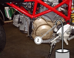
Remove the filler plug (2) and top up with the recommended oil.
Refit the plug (2).
Changing the engine oil and filter cartridge
Note
Change the oil when the engine is hot (but off). In these conditions the oil is more fluid and will drain more rapidly and completely.
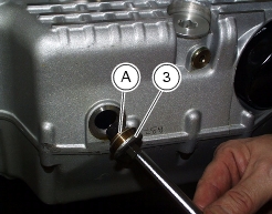
Remove the drain plug (3) - keep the seal (A) - on the crank sump and allow the oil to drain off.
Warning
Dispose of oil and/or filter cartridges in compliance with environmental protection regulations.
Remove any metallic deposits from the end of the magnetic drain plug (3). Refit the drain plug complete with seal (A) to the sump.
Tighten it to the specified torque (Sect. C 3,
Engine torque settings
).
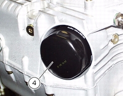
With a common filter wrench, remove the filter cartridge (4) from the oil sump.
Caution
Dispose of used cartridge. Do not reuse cartridges.
Grease the seal with engine oil and then fit the new cartridge (4).
Note
It is recommended to fill the filter cartridge (4) with oil before installation and you will not need to top up level later.
Screw it in its seat and tighten to the specified torque (Sect. C 3,
Engine torque settings
).
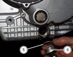
Clean the oil mesh filter every second oil change.
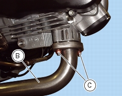
Loosen the outer plug (6) and the seal (5).
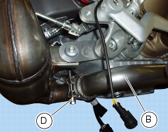
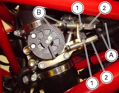
To perform this operation, it is first necessary to remove the horizontal head exhaust pipe (B) by removing nuts (C) and clamp (D).
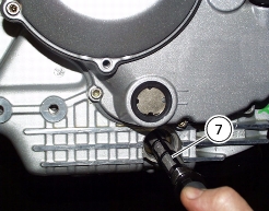
Release and withdraw the mesh filter (7).
Clean the mesh filter with gasoline and compressed air. Care must be taken not to break the filter mesh.
Refit the mesh filter (7) and its seal (5) on the plug (3) and tighten to the specified torque (Sect. C 3,
Engine torque settings
).
Remove the filler plug (2) and fill with the recommended oil (Sect. C 2,
Fuels and lubricants
). Fill until the oil reaches the MAX mark on the sight glass.
Refit the filler plug (2). Run the engine at idling speed for several minutes.
Check for oil leaks. Check that the oil pressure light on the instrument panel switches off several seconds after the engine has
been started. If this is not the case, switch off and trace the fault.
Switch off the engine and allow several minutes for the oil to settle. Check the oil level and top up to MAX mark, if necessary.
Refit any parts you have removed.
Checking valve clearances
Proceed as described under Section N 4.1,
Checking and adjusting valve clearance
.
With the valve in the rest position, slide a feeler gauge between opening rocker arm and shim to measure clearance.
Values must be as follows:
Opening rocker arm
Intake
:
(A)
Nominal
0.10-0.15 mm
In operation
0.05-0.15 mm
Exhaust
:
(A)
Nominal
0.10-0.15 mm
In operation
0.05-0.15 mm
With the valve in the rest position, slide a feeler gauge between closing rocker arm and shim to measure clearance. Clearance
must be within the specified limits:
Closing rocker arm
Intake
:
(B)
Nominal
0-0.05 mm
In operation
0-0.20 mm
Exhaust
:
(B)
Nominal
0-0.05 mm
In operation
0-0.20 mm
If the clearances measured are outside the specified limits, measure clearance and adjust as required (Sect. N 4.1,
Checking and adjusting valve clearance
).
Adjusting valve clearances
Proceed as described under Section N 4.1,
Checking and adjusting valve clearance
.
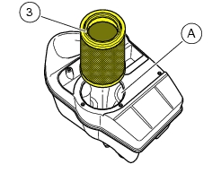
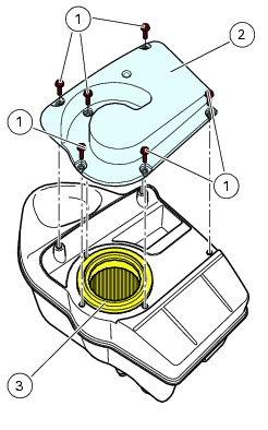
Changing and cleaning the air filter
The air filter must be changed at the intervals indicated in the "
Routine maintenance table
" (Sect. D 3).
Remove the fuel tank (Sect. L 2,
Removing the fuel tank
).
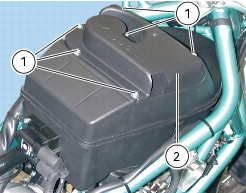
Release the six retaining screws (1) of the air box cover (2).
Remove the cover (2).
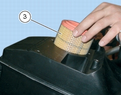
Remove the filtering cartridge (3).
Blow the filter cartridge with compressed air or replace it if unserviceable.
Caution
A clogged air filter will reduce air intake and engine power leading to increased fuel consumption, and cause a build up of scale
on the spark plugs. Do not run the engine without the air filter. Running the engine without a filter will draw impurities into the engine and may damage the engine.
Fit the filter cartridge (3) into its seat (A) in the filter box cover and refit all components previously removed. In particular, tighten
the screws (1) to the specified torque (Sect. C 3,
Frame torque settings
): follow a cross pattern.
Caution
If the vehicle is used in very damp or dusty conditions, the air filter cartridge must be changed more frequently.
Changing the brake fluid
Warning
Brake fluid will damage painted surfaces if spilled on them. In addition, it will cause severe injury if spilled on the skin or into your
eyes. In the event of accidental contact with skin or eyes, wash the affected area with abundant running water.
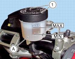
Changing the front brake fluid
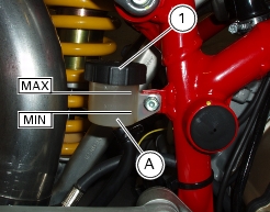
Undo the screws (1) and remove the diaphragm cover from the front brake reservoir.
Suck the oil up from the reservoir (A).
Fill reservoir (A) with fresh oil up to MAX level.
Pump up two or three times with the lever to pressurize the circuit.
Keep the lever pulled toward the handgrip.
Connect a clear hose to the bleed valve (2); put one end of the hose into a container on the floor.
Loosen the bleed valve (2) so that oil flows off.
Warning
When filling up, keep oil level above MIN mark to avoid air being trapped into the circuit.
Let oil flow off from the bleed valve (2) until of different color.
Tighten the bleed valve (2) to the specified torque (Sect. C 3,
Frame torque settings
) and top up oil to correct level.
Note
Repeat the above procedure for both calipers.
Refit the diaphragm cover from the front brake reservoir and tighten the screws (1).
Changing the rear brake fluid
Remove the rear wheel as specified in Sect.
G 4,
Removing the rear wheel
.
Unscrew cover (1) and remove diaphragm inside rear brake fluid reservoir (A).
Suck the oil up from the reservoir (A).
Remove the rear brake caliper as described under Sect.
G 6,
Removing the rear brake system
; hold it as high as possible and fit a shim in-between the pads of thickness equal to brake disc.
Fill reservoir (A) with fresh oil up to MAX level.
Pump up two or three times with the pedal to pressurise the circuit.
Hold the pedal pressed.
Connect a clear hose to the bleed valve (2); put one end of the hose into a container on the floor.
Warning
When filling up, keep oil level above MIN mark to avoid air being trapped into the circuit.
Let oil flow off from the bleed valve (2) until of different color.
Tighten the bleed valve (2) to the specified torque (Sect. C 3,
Frame torque settings
) and top up oil to correct level.
Refit the caliper as described in Sect.
G 6,
Refitting the rear brake system
and then refit the rear wheel as specified in Sect. G 4,
Refitting the rear wheel
.
Refit the cover (1) on the rear brake cylinder reservoir (A).
Draining the brake circuits
Warning
Brake fluid will damage painted surfaces if spilled on them. In addition, it will cause severe injury if spilled on the skin or into your
eyes. In the event of accidental contact with skin or eyes, wash the affected area with abundant running water.
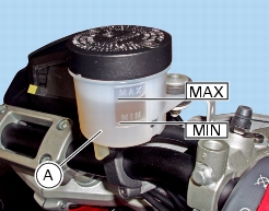
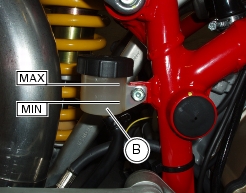
Undo the screws (2) and remove the diaphragm cover (1) from the front brake reservoir (A).
Remove the cover (3) from the rear brake cylinder reservoir (B).
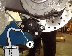
Connect a common brake bleeder, easily available on the market, to the bleed valve (4) or (5).
Note
If you are using a commercial bleeder, always follow the manufacturer's instructions.
Unscrew the bleed valve (4) or (5) and pump the brake bleeder until all the fluid has fully drained off the circuit.
If you do not have a brake bleeder available, attach a length of transparent plastic tubing to the caliper bleed valve (4) or (5) and
put the other end of the hose into a container holding spent brake fluid you will have placed on the floor.
Unscrew the bleed valve by one fourth of a turn.
Operate the brake lever (or pedal) until all the fluid has fully drained off the circuit.
Repeat this operation for each brake caliper.
Filling the brake circuits
Warning
Brake fluid will damage painted surfaces if spilled on them. In addition, it will cause severe injury if spilled on the skin or into your
eyes. In the event of accidental contact with skin or eyes, wash the affected area with abundant running water.
Fill the reservoirs (A) and (B) with specified brake fluid (Sect. C 2,
Fuels and lubricants
) from a sealed container.
Caution
During the next operation, the fluid level must remain topped up at all times. The end of the transparent plastic tubing must
remain immersed in the discharged fluid at all times.
Operate the brake lever (or pedal) several times to let the fluid reach all points of the circuit and expel any air.
Note
Remove the rear wheel (Sect.
G 4,
Removing the rear wheel
) and then remove the rear brake caliper as described in Sect. G 6,
Removing the rear brake system
.
Hold it as high as possible and fit a shim in-between the pads of thickness equal to brake disc.
Connect the bleeder to bleed valve (4) or (5) of brake caliper.
Note
If you are using a commercial bleeder, always follow the manufacturer's instructions.
Pump the brake bleeder and slacken the bleed valve (4) or (5). Make sure the level stays above the MIN level at all times.
Repeat the bleeding operation until air bubbles no longer come out of the plastic tube.
Tighten the bleed valve (4) or (5) to the specified torque (Sect. C 3,
Frame torque settings
).
If you do not have a brake bleeder available, connect a length of transparent plastic tubing to the bleed valve as outlined in the
draining procedure.
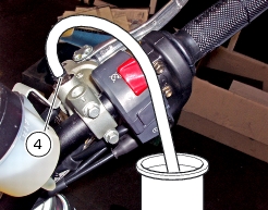
Open the bleed valve (4) or (5) by one fourth of a turn and operate the brake lever (or pedal) several times until the fluid starts
coming out of the bleed valve.
Pull the lever or pedal fully in and slacken the bleed valve by at least one fourth of a turn.
Allow several seconds and then release the lever (or pedal) gradually and close the bleed valve.
Caution
Do not release the brake lever (or pedal) until the bleed valve has been fully tightened.
Repeat the bleeding operation until air bubbles no longer come out of the plastic tube.
Bleed all bleed valves on the calipers one at a time.
Tighten the bleed valve (4) or (5) to the specified torque (Sect. C 3,
Frame torque settings
). Fit the protection cap.
To completely bleed air that can be in the front brake master cylinder highest point, proceed in the same way on bleed valve (4).
Top up fluid in reservoir and refit any removed parts.
Changing the clutch fluid
Warning
Clutch fluid will damage painted surfaces if spilled on them. In addition, it will cause severe injury if spilled on the skin or into your
eyes. In the event of accidental contact with skin or eyes, wash the affected area with abundant running water.
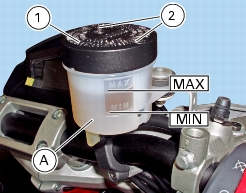
Undo the screws and remove the diaphragm cover (1) from the clutch reservoir (A).
Suck the oil up from the reservoir (A).
Fill reservoir (A) with fresh oil up to MAX level.
Pump up two or three times with the lever to pressurize the circuit.
Keep the lever pulled toward the handgrip.
Connect a clear hose to the bleed valve (2); put one end of the hose into a container on the floor.
Loosen the bleed valve (2) so that oil flows off.
Warning
When filling up, keep oil level above MIN mark to avoid air bubbles into the circuit.
Let oil flow off from the bleed valve (2) until of different color.
Tighten the bleed valve (2) to the specified torque (Sect. C 3,
Frame torque settings
) and top up oil to correct level.
Draining the clutch circuit
Warning
Clutch fluid will damage painted surfaces if spilled on them. In addition, it will cause severe injury if spilled on the skin or into your
eyes. In the event of accidental contact with skin or eyes, wash the affected area with abundant running water.
Slip off the protective cap to expose the bleed valve (2).
Connect a bleeder to the bleed valve (2) on the transmission unit.
Note
If you are using a commercial bleeder, always follow the manufacturer's instructions.
Unscrew the bleed valve and pump the bleeder until all the fluid has fully drained off the circuit.
If you do not have a bleeder available, connect a piece of transparent plastic tubing to the bleed valve (2). Place the other end in
a container on the floor holding used clutch fluid.
Unscrew the bleed valve by one fourth of a turn.
Remove the diaphragm cap (1) from reservoir (A).
Operate the clutch lever until all the fluid has fully drained off the circuit.
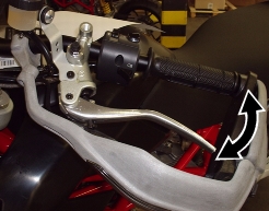
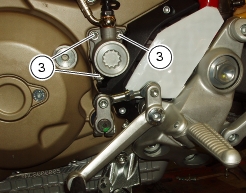
To help drain the circuit fully, unscrew the three retaining screws (3) of the transmission unit and remove from engine
.
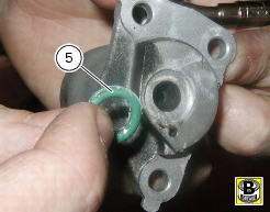
Withdraw the clutch transmission unit (4). Be careful of the O-ring (5) placed inside.
Push in the piston to expel all fluid inside the unit.
Refit transmission unit and tighten the retaining screws (3) to the specified torque (Sect. C 3,
Frame torque settings
).
Tighten the bleed valve to the specified torque (Sect. C 3,
Frame torque settings
). Fit the protection cap.
Filling the clutch circuit
Warning
Clutch fluid will damage painted surfaces if spilled on them. In addition, it will cause severe injury if spilled on the skin or into your
eyes. In the event of accidental contact with skin or eyes, wash the affected area with abundant running water.
Fill the reservoir with specified fluid (Sect. C 2,
Fuels and lubricants
) taken from a sealed container.
Caution
During the next operation, the fluid level must remain topped up at all times. The end of the transparent plastic tubing must
remain immersed in the discharged fluid at all times.
Operate the clutch lever several times to let the fluid reach all points of the circuit and expel any air.
Connect the bleeder to the bleed valve (2).
Note
If you are using a commercial bleeder, always follow the manufacturer's instructions.
Pump with the bleeder and slacken the bleed valve (2). Ensure the fluid level never drops below the
MIN
level.
Repeat the bleeding operation until air bubbles no longer come out of the plastic tube connected to the bleed valve (2).
If you do not have a bleeder available, connect a length of transparent plastic tubing to the bleed valve (2) as outlined in the
draining procedure.
Open the bleed valve (2) by one fourth of a turn and operate the clutch lever several times until the fluid starts coming out of the
bleed valve (2).
Pull the lever fully in and slacken the bleed valve by at least one fourth of a turn.
Allow several seconds and then release the lever gradually and close the bleed valve (2).
Caution
Do not release the clutch lever until the bleed valve has been fully tightened.
Repeat the bleeding operation until air bubbles no longer come out of the plastic tube.
Tighten the bleed valve (2) to the specified torque (Sect. C 3,
Frame torque settings
). Fit the protection cap.
Top up the clutch fluid up to
3
mm above the
MIN
mark.
Refit the filler plug (1) with diaphragm
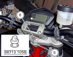
Adjusting steering bearing play
Excessive handlebar play or shaking forks in the steering head indicate that the play in the steering head bearings requires
adjustment. Proceed as follows:
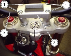
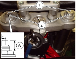
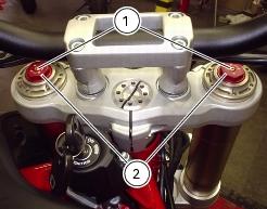
Loosen the four screws (1) and remove the U-bolt (2), slide off the handlebar (3) from steering head and set it so that it does not
hinder any of the following operations.
Loosen the screws (4) on the steering head at the fork leg clamps.
Loosen the clamp screw (5) securing the steering tube to the steering head.
Tighten the ring nut (6) to the specified torque (Sect. C 3,
Frame torque settings
) using the tool part no.
88713.1058
.
Tighten all the previously loosened screws to the specified torque (Sect. C 3,
Frame torque settings
).
Reposition the handlebar, fit the two U-bolts (2) and tighten the four U-bolt screws (1) to the specified torque (Sect. C 3,
Frame torque settings
).
Turn handlebar fully to ensure that bearings play is correct.
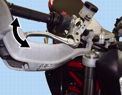
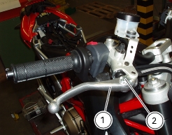
Adjusting the clutch lever and front brake lever
The lever (1) controls the front brake and has a dial adjuster (2) to adjust the lever distance from the throttle twistgrip on the
handlebar.
Hold the lever (1) completely forward and turn knob (2) to one of the four positions available; consider that position 1 sets
maximum gap from lever to handgrip, while position 4 sets minimum gap.
The same adjustment procedure also applies to the clutch lever.
When you pull in the clutch lever, you will disengage the engine drive from the gearbox and therefore from the driving wheel.
Using the clutch properly is essential to smooth riding, especially when moving off.
Warning
Clutch and brake levers must be adjusted when the motorcycle is stopped.
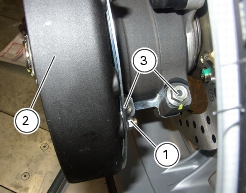
Adjusting chain tension
Wheel the motorcycle back and forth until finding the position at which the chain is tightest.
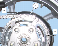
Set the motorcycle on the side stand and measure the gap between swingarm and chain lower section middle, at the most
forward point of the chain guard. The gap should be within the range
38
to
42
mm, as indicated on the nameplate stuck on swingarm.
If not so, rectify as follows:
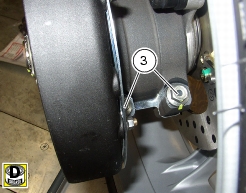
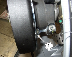
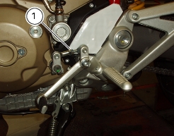
loosen nuts (1) securing the chain guard (2) to bracket so that screws (3) -securing the rear hub to swingarm- can be loosened.
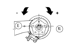
Fit an extension to supplied wrench and insert its tab into the eccentric hub.
Rotate the eccentric hub until achieving correct chain tension. Rotate clockwise to tension up the chain; rotate counter clockwise
to slacken. (When viewed from chain side).
Caution
Wheel axis (R) must remain below eccentric hub axis (E) during the whole operation.
Smear recommended grease on underside and thread then tighten screws (3) to the specified torque (Sect. C 3,
Frame torque settings
), proceeding in a 1-2-1 sequence.
Warning
Correct tightening of the eccentric hub bolts is of fundamental importance for the rider's and passenger safety.
After tensioning the chain, position chain guard (2) ensuring that gap from chain is even all over its outer edge.
Tighten to the specified torque (Sect.
C 3,
Frame torque settings
) the nuts (1) and refit the rear wheel as described in Sect. G 4,
Refitting the rear wheel
.
Checking brake pad wear. Changing brake pads
Warning
Brake fluid will damage painted surfaces if spilled on them. In addition, it will cause severe injury if spilled on the skin or into your
eyes. In the event of accidental contact with skin or eyes, wash the affected area with abundant running water.
Caution
Please inform the Customer that new pads must be run-in carefully
– in other words, the front brake must be used carefully for the first 100 Km to allow the friction material to bed in completely.
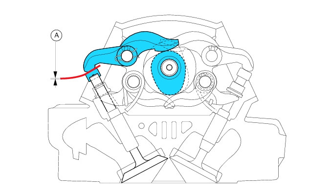
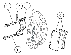
Checking front brake wear
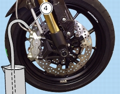
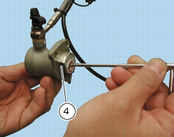
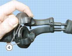
Look through the slot in the caliper clip (1) to make sure the groove in the brake pad friction material (4) has not worn out.
Caution
If one of the pads is worn, change both pads.
Change the brake pads as follows.
Remove the safety split pin (2) from the inner end of pad retaining pins.
Withdraw the pad retaining pins (3) outward.
Remove the brake pad retaining clip (1) from between the two caliper halves.
Force the brake pads apart to force the caliper pistons into their housings.
Remove the worn pads (4) from caliper.
Note
Change pads which are shiny or vitrified.
Insert the new pads and the clip (1) to caliper.
From caliper outside, install centring pins (3) and lock them in place using split pin (2).
Operate the brake lever repeatedly so that the pads bed in under the action of the brake fluid.
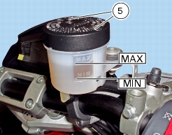
Make sure that the level inside cylinder reservoir is not below the
MIN
notch. If the level is too low, top up as follows. Turn the handlebar so that the reservoir is level.
Unscrew the screws (5) and remove the reservoir cover.
Remove the inner membrane from the reservoir.
Top up to max level (MAX) using the specified fluid.
Reassemble.
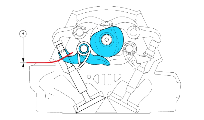
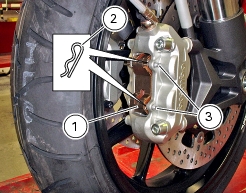
Checking rear brake wear
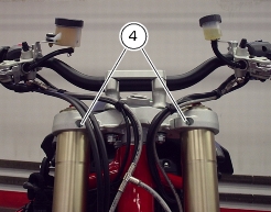
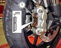
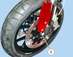
Remove the front brake calipers from the fork removing screws (1). Make sure the groove (A) in the brake pad friction material
(4) has not worn out.
Caution
If one of the pads is worn, change both pads.
To change the pads, proceed as follows:
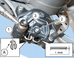
Remove the split pin (1) from the caliper retaining pin (2). The split pin is on caliper inner side. Withdraw the brake pad retaining
pin (2) and pull it out.
Remove the brake pad retaining clip (3) from between the two caliper halves.
Force the brake pads apart to force the caliper pistons into their housings. Remove the worn pads.
Note
Change pads which are shiny or vitrified.
Insert the new pads and the clip (3) to caliper. Insert the retaining pin (2) from outside and push it fully home. Fit the split pin (1)
with the end (A) pointing to the wheel.
Operate the brake pedal repeatedly so that the pads bed in under the action of the brake fluid. Make sure that the level inside
the reservoir is between the
MIN
and
MAX
. notches. If this is not the case, loosen reservoir cap (4) and top up.
Note
In case of difficulties with pads replacement, remove the caliper (Sect. G 4,
Removing the rear wheel
).
Warning
The brake calipers are critical safety components. Observe the instructions given in Sect. G 3,
Front brake
, and Sect. G 6,
Rear brake
. Be sure to tighten the brake caliper mounting bolts to the specified torque on refitting (Sect. C 3,
Frame torque settings
).
Adjusting the throttle cables
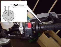
The throttle twistgrip must have a free travel of
1.5-2
mm (measured on the twistgrip rim) in all steering positions.
To adjust throttle twistgrip travel you need to slide off the rubber covers (A) and caps (B) from their seats.
Loosen the lock nuts (1), remember that the bottom one opens the throttles while the top one closes them; work adjuster (2) to
set required play.
Tighten both lock nuts (1) and refit covers (A) and caps (B) onto adjusters (2).
Periodically check opening and closing cables sheaths for wear. The outer plastic cover should not be flattened or cracked.
To ensure smooth operation of these cables, grease the cable ends with the recommended grease at regular intervals.
Work the control to make sure core cable is sliding smoothly. If not so, change the cable.
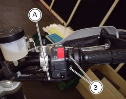
To lubricate the throttle control, slightly slide out rubber cap (A), unscrew the screws (3) and open control (4).
Grease the cable end and the pulley.
Carefully close the control (4) routing cable in the two shells.
Tighten the screws (3) to the specified torque (Sect. C 3,
Frame torque settings
).
Refit rubber (A) in its seat.
Adjusting the position of the gear change and rear brake pedals
The position of the gear change and rear brake pedals in relation to the footpegs can be adjusted to suit rider preferred position.
Gear change pedal
To adjust the position of the gear change pedal, proceed as follows:
Apply an open-end wrench to the flats (A) to lock out fixed joint (1) rotation and loosen the check nut (2).
Unscrew the screw (4) to release the mobile joint (3) from the gear change lever.
Turn the mobile joint (3), until gear change pedal is set to desired position.
Secure the gear change lever to the mobile joint (3) with the screw (4).
Tighten the check nut (2) onto the fixed joint (1).
Rear brake pedal.
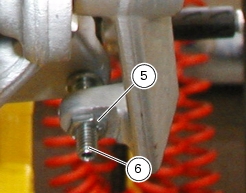
Loosen check nut (5).
Turn pedal travel adjusting screw (6) until pedal is in the desired position.
Tighten check nut (5).
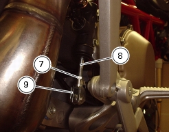
Work pedal by hand to make sure it has 1.5 - 2 mm free play before brake begins to bite.
If not so, set the length of cylinder push-rod as follows.
Loosen the check nut (7) on cylinder linkage.
Tighten linkage (8) onto fork (9) to increase play, or unscrew linkage to reduce it.
Tighten the lock nut (7) and check the amount of pedal free travel.
Adjusting the front fork (1100)
The front fork used on this motorcycle has rebound, compression and spring preload adjustment.
This adjustment is done using the outer adjusters:
1) rebound damping;
2) inner spring preload;
3) compression damping.
Place the motorcycle on the side stand and ensure it is stable.
Turn the adjuster (1) at the top end of each fork leg with a flat screwdriver to adjust rebound damping.
Turn the adjuster (3) at the rear end of the wheel shaft pinch bolts with a flat screwdriver to adjust compression damping.
As you turn the adjuster (1) and (3), you will hear them click. Each click identifies a setting. Tighten the adjuster fully to achieve
the hardest damping. This will be your starting point. Now turn the adjuster counter clockwise and listen for the clicks that identify setting positions no. 1, 2 and so on.
STANDARD factory setting is as follows:
Compression: 1.5 turns ± 1/4 of a turn
Rebound: 1.5 turns ± 1/4 of a turn
Spring preload (A): 10
mm (3 turns from the fully open position).
To change the preload of the spring inside each fork leg, turn the hex. adjuster (2) with a 22-mm hexagon wrench.
Caution
Adjust both fork legs to same settings.
Adjusting the front fork (1100S)
The front fork has rebound, compression and spring preload adjustment.
This adjustment is done using the outer adjusters:
1
rebound damping;
2
inner spring preload;
3
compression damping.
Place the motorcycle on the side stand and ensure it is stable.
Turn the adjuster (1) at the top end of each fork leg with a flat screwdriver to adjust rebound damping.
Turn the adjuster (3) at the rear end of the wheel shaft pinch bolts with a flat screwdriver to adjust compression damping.
As you turn the adjuster (1) and (3), you will hear them click. Each click identifies a setting. Tighten the adjuster fully to achieve
the hardest damping. This will be your starting point. Now turn the adjuster counter clockwise and listen for the clicks that identify setting positions no. 1, 2 and so on.
STANDARD factory setting is as follows:
Compression:
1.5 turns ± 1/4 of a turn
Rebound:
1.5 turns ± 1/4 of a turn
Spring preload:
10 mm (3 turns from the fully open position).
To change the preload of the spring inside each fork leg, turn the hex. adjuster (2) with a 22-mm hexagon wrench.
Caution
Adjust both fork legs to same settings.
Adjusting the rear shock absorber (1100)
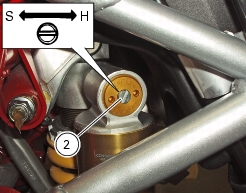
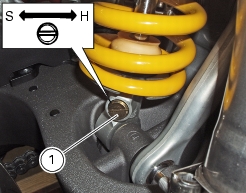
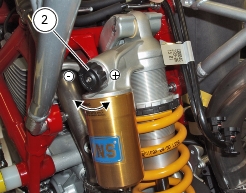
The rear shock absorber has outer adjusters that enable you to adjust your motorcycle to the load.
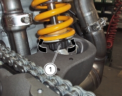
The adjuster (1) on the right side of the connection holding the shock absorber to the swinging arm controls rebound damping.
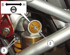
The adjuster (2) on the shock absorber expansion reservoir controls compression damping.
Turning the adjusters (1) and (2) clockwise gives harder damping, turning counter clockwise gives softer damping.
STANDARD setting from the fully closed position (turn clockwise):
-
undo adjuster (1) by 15 clicks
± 3 clicks.
-
undo adjuster (2) by 2 turns
± 1/4 of a turn.
Spring preload: 19 mm.
The two ring nuts (3), positioned on rear shock absorber upper part, are used to adjust outer spring preload. To change spring
preload, loosen upper locking ring nut.
Screw
or
loosen
lower ring nut to
increase
or
decrease
spring preload.
Warning
The shock absorber is filled with gas under pressure and may cause severe damage if taken apart by unskilled
persons.
Caution
When carrying a passenger and a load, set maximum spring preload for improved handling and to keep safe ground clearance.
Set rebound damping accordingly.
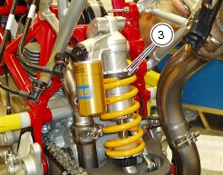
Adjusting the rear shock absorber (1100S)
The rear shock absorber has outer adjusters for setting motorcycle so to match load conditions.
The adjuster (1) on the right side of the connection holding the shock absorber to the swinging arm controls rebound damping.
The adjuster (2) is on the expansion chamber of the shock absorber and sets compression damping.
Turn the adjusters (1) and (2) clockwise for harder damping and counter clockwise for softer damping.
Standard setting:
Undo adjusters from the fully closed position (turn clockwise):
adjuster (1) by 15
clicks;
adjuster (2) by 7
clicks.
Spring preload: 19
mm.
The two ring nuts (3), positioned on rear shock absorber upper part, are used to adjust outer spring preload. To change spring
preload, loosen upper locking ring nut.
Screw
or
loosen
lower
ring nut to
increase
or
decrease
spring preload.
Warning
The shock absorber is filled with high-pressure gas and might cause injuries if inexpertly dismantled.
Changing motorcycle track alignment (1100S)
Motorcycle track alignment as set at the factory is the result of tests carried out under different riding conditions by DUCATI test
riders. Modifying factory setting is a very delicate operation, which may lead to serious damages if carried out by unskilled people. Since this motorcycle is often used in competitions, DUCATI saw it fit to equip it with special mechanisms to modify rear suspension and steering head geometry to suit all kinds of track conditions.
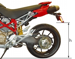
Changing the tail height
Determine motorcycle track alignment as follows.
Place the motorcycle on level ground and keep it upright.
Measure the distance (h). Note the measurement in order to restore the original setting later on.
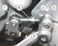
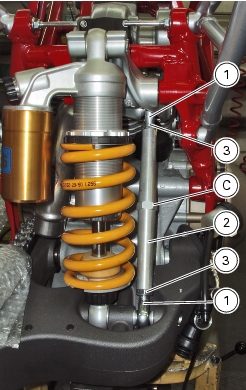
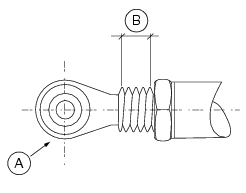
Distance (h) may be modified by varying the length of the linkage (2) as follows:
Slacken the lock nuts (3) on the ball joints (1). Note that the
lower nut has a left hand thread
.
Rotate the linkage (2) fitting a wrench (C) to the flats in the centre until obtaining the desired dimension.
Warning
The length of linkage (2) as measured across the centres of ball joints (1) should never exceed
255.5
mm.
Tighten the lock nuts (3) to the specified torque (Sect. C 3,
Frame torque settings
).
Ball head (A) UNIBALL max. protruding portion is of 5 threads, i.e. 7.5 mm (B).