3 -
Note
Following reference numbers refer to "Wiring diagram", Sect. P 1.
Electric starting system
The key components of the electric starting system are a starter contactor (1) and a starter motor (2) fed by the battery (3).
ECU (4) has total control on motorcycle ignition procedure. It monitors the following inputs:
-
-
-
-
-
 
If all above inputs send enabling signals, the control unit (4) will enable engine ignition procedure.
The table shows possible ignition combinations.
 
If all inputs are in OK status, the control unit will enable the starter motor (ON) when START is pressed.
X = generic status of neutral, clutch and stand.
Safety devices function table
 
 
Starter motor
Power:
0.7 kW/12 V
Direction of rotation:
counter clockwise viewed from power take-off side.
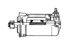
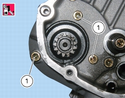
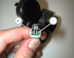
As the starter motor is reliable and compact, it usually does not fail. In case of troubles, ensure that the starter motor cable terminal is properly tightened under the nut and shows no oxidation. If the terminal is properly tightened and free from oxidation, remove the starter motor and test it under loadless conditions (no load applied to the shaft). Secure the starter motor to a test bench. Ensure not to damage motor case. Use a 12V fully-charged battery. Take battery-motor connection cables not longer than 70 cm and having the same cross-section as the motorcycle connection cable. Connect the negative terminal of the battery with an unpainted area of the motor case and the positive terminal to its electric terminal. The motor shaft should rotate quickly and freely. Proceed with utmost care so not to short-circuit cables which are connected to the battery.
Removing the starter motor
Remove generator cover (Sect. N 8, Removing the generator cover).
In the event the whole starting gears unit needs replacing, remove timing intermediate gears and starter motor intermediate gear (Sect. N 9.1, Removing the starter motor driven gear).
Disconnect starter motor / starter contactor cable (3) (see diagram in "Arrangement of wiring on frame", Sect. P 1).
Undo retaining screws (1).
Note
Starter motor retaining screws are originally assembled with threadlocker.
 
Slide out starter motor and gasket (2).
Refitting the starter motor
Visually inspect gasket (2) for wear. Replace if necessary.
Place gasket (2) and starter motor on casing and tighten screws (1) to the specified torque (Sect. C 3, Engine torque settings).
Connect starter motor / starter contactor cable (3).
Caution
Fill the protective cap with protective grease before fitting it on the starter motor.
 
If the starting gears assembly was replaced, refit starter motor intermediate gear and timing intermediate gears (Sect. N 9.1, Reassembling the starter motor driven gear).
Close the generator cover (Sect. N 8, Reassembling generator cover).
Starter contactor
Starter contactor (1) is connected to the tank.
Disconnect the battery (Sect. P 2, Battery).
Remove the solenoid starter from its housing into the battery support.
Undo the nuts (3) and collect the spring washers (4).
Remove the contactor-starter motor cable (5).
Remove the contactor-battery cable (6).
Disconnect solenoid starter connector (2) from wiring (see diagrams in “Arrangement of wiring on frame”, Sect. P 1).
Remove the protection caps (A).
Starter contactor operational check
Apply a 12V (battery) across the positive (A) and negative (B) terminals of the connector.
Connect a multimeter between the two poles [threaded pins (+) and (-)] of the starter contactor and then check for electric continuity (Sect. P 9, Test equipment). If continuity is not ensured, replace the starter contactor.
Set cables (5) and (6) onto starter contactor poles.
 
At reassembly, check that contacts (+) and (-) are not oxidized and use waterproof spray.
Tighten the nuts (3) to the specified torque (Sect. C 3, Engine torque settings).
Refit the connector (2) to wiring (Sect. P 1, Arrangement of wiring on frame).
Refit the protection cover.
Fit the solenoid starter to the tank: push solenoid starter fully home, i.e until the four support tabs come out on the solenoid starter side.