2 -
Charging system – battery
Checking the charging system
To check the current flow in the charging circuit, use the "DDS" tester with the supplied inductive clamp-type amperemeter.
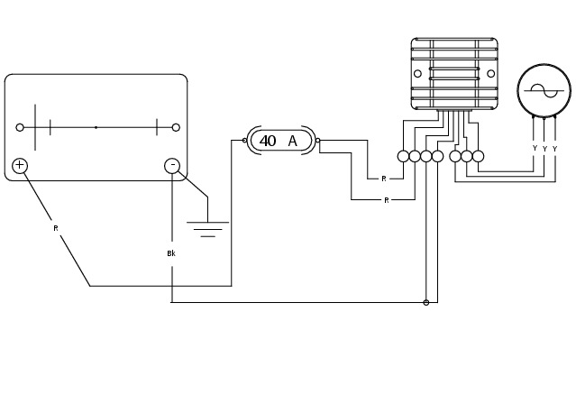
please refer to “Checking the charging system”, Sect. D 5. Using the "DDS" test equipment, you can determine the engine rpm required for generator to produce just enough current to charge battery, feed the injection-ignition system and all electric items fitted to motorcycle. When applied to a cable, the amperemeter clamp detects the magnetic field generated by the current passing through that cable. Test equipment automatically calibrates by means of its own transducer.
If the measured current is a positive quantity, it means that generator is feeding all electric items and charging battery at the same time. A negative value means that charging system is not feeding the loads and a significant amount of current is supplied to the battery, currently discharging.
Or it is possible to use a multimeter (Sect. P 9, Test equipment): connect probes from multimeter to battery terminals, select the direct current position on the multimeter; the reading should be 14.50.5 at 3000 rpm.
Caution
If polarity is reversed when clamping amperemeter onto cable, readings polarity will also be reversed. This will lead to wrong diagnosis.
 
Recharging the battery
Check the inspection interval indicated on the label.
Charge battery if open circuit voltage is lower than 12.8 V. Leaving the battery discharged for more than one month could damage the battery itself. Check battery charge with a voltmeter.
Always check battery condition before charging and 1 - 2 hours after charging.
Caution
Strictly follow the recharging time indications. Immediately stop charging the battery if it becomes too hot. Let it cool down before resuming the charging operations.
 
Use only constant-voltage battery chargers.
Check that battery terminals are properly connected to battery charger.
To charge battery, proceed as follows:

Use fast charge for emergencies only.
Long periods of inactivity
If battery voltage is 11.5 V or lower, it needs charging.
Connect the battery charger to the battery.
Use a voltage of 16-17V.
In case the ammeter does not show any change, increase voltage to maximum 25V.
Charge for 5 min.
In case the ammeter shows a change, take voltage back to 16-17 V, or change the battery.
Adding electrolyte
Remove the battery from the vehicle.
Warning
Carefully read the relevant safety rules before making any intervention on the battery (Sect. A 3, General safety rules).
The battery fluid is toxic and might cause burns if it gets in contact with your skin, because it contains sulphuric acid.
Wear protective clothes, a face mask and goggles before proceeding.
If the fluid gets in contact with the skin, immediately wash with running water. If the fluid gets in contact with your eyes, wash with abundant running water for 15 minutes and immediately seek specialised medical advice. If it is accidentally swallowed, drink a lot of water or milk, then magnesia milk, beaten eggs or vegetable oil. Keep the battery away from sparks, flames, cigarettes or any other heat source, because it gives off explosive gases.
Ventilate the room when charging the battery or using the battery indoors. Do not breathe the gas given off while charging the battery.
KEEP AWAY FROM CHILDREN.
 
Set the battery on a flat surface. Remove the protective film (1).
Warning
Ensure that the fluid is suitable for your battery.
Take the fluid container off the vinyl case. Remove the cap bar (3) from the container (2).
Caution
Keep the cap bar (3) at hand because it will be used to plug the battery cells.
Warning
Do not graze or pierce the sealed areas.
 
Set the fluid container (2) upside-down. Ensure the six sealed elements match the six filler holes on the battery.
Push down the container (2) and break the seals so that fluid can flow out.
Note
Do not tilt the fluid container or the flow might stop.
Ensure that air bubbles come out from all six holes. Let the container in this position for more than twenty minutes.
Should no air bubbles show from one of the filler holes, slightly tap on the bottom of the corresponding bottle.
Caution
Always keep container stuck to battery. Do not cut or pierce the bottle.
 
Ensure that all fluid has flown off. Lightly tap on the bottom of container (2) to help drain out all fluid. Carefully remove the container (2) from the battery.
Fit the cap bar (3) -previously removed from the electrolyte container (2)- to the battery, ensure the caps plug off all filler holes.
3 -12 Ah batteries: allow at least 30 min.
>12 Ah batteries: allow at least 1 hour.
 
Set the bar with the caps onto filler holes without fastening it. Recharge the battery as described under “Recharging the battery”.
Note
When using an automatic-reduction battery charger, check that the charger current (amperes) is equal or higher than the value of standard charging system (STD) indicated on the battery itself.
Press down with both hands to ensure caps are correctly seated
(do not use a hammer).
Battery
Battery safety rules
Warning
Carefully read the relevant safety rules before making any intervention on the battery (Sect. A 3, General safety rules). When under charge, batteries produce explosive gases. Keep batteries away from heat sources or open flames.
Instructions for use of the battery
This is a sealed-type maintenance-free battery, ready for installation to the vehicle.
Note
Keep the battery clean. Smear grease on the battery terminals to prevent corrosion.
Warning
Do not remove the valve sealing bar on the top of the cover or top up fluid. Replace battery if block, cover and terminals are broken or if the valve cover has been disturbed.
Caution
If the motorcycle is left unused for more than 30 days, remove the battery and store it in a safe, cool place.
 
Always charge the battery before the first operation and after long storage periods – such as before selling the vehicle.
Removing the battery
Note
References (48) and (44) are the same as those of diagrams under “Arrangement of wiring on frame” of Sect. P 1.
 
Remove the seat (Sect. E 3, Removing the seat).
Undo the screws on the terminals (48) and (44) and remove the battery. Always start from the negative terminal.
Refitting the battery
Install the battery on its mount within the fuel tank.
Tighten terminal screws (48) and (44) to the specified torque (Sect. C 3, Frame torque settings) and use a waterproof spray.
Refit the seat (Sect. E 3, Refitting the seat).
Generator
The generator is a 12V, 520W alternator, consisting of a fixed stator (A) located in the generator cover and a rotor (B) fixed to the crankshaft.
Note
To check operation of the battery charging system, use the DDS, please refer to "Checking the charging system" (Sect. D 5).
 
Absolute value of voltage measured across the terminals of two of the three yellow cables (measured value will be the same whichever the combination) must be within the range indicated in the table below.
(Ambient temperature: 20 °C)
Caution
Disconnect generator cables from the electric system when the ignition key is positioned to OFF before testing.
27±10
78±10
Values notably lower than the mentioned values can be due to:
partially demagnetized rotor;
short-circuited coil windings.
 
In the above cases the whole generator assembly (rotor and stator) should be replaced.
If checks have a favourable outcome, reconnect generator to regulator with ignition key on OFF. Make sure that no cables are damaged or disconnected.
Removing the generator
Disconnect the generator-side electrical cables (see diagram in "Arrangement of wiring on frame", Sect. P 1).
Remove generator cover, stator (A) and rotor (B) (Sect. N 8, Removing the generator cover).
Refitting the generator
Fit rotor (B), stator (A) and generator cover.
Connect the generator-side electrical cables (see diagram in "Arrangement of wiring on frame", Sect. P 1).
Rectifier - regulator
Rectifier (1) is fastened to the frame.
The rectifier-regulator consists of an aluminium casing containing the diodes that rectify the current produced by the generator. It also has an electronic device controlling the power supplied by the generator depending on battery voltage.
If the battery is flat, value of power supplied can set the battery to its original optimal operating conditions.
If the battery is charged, power value will be lower.
Note
To check recharging current, use the DDS, please refer to "Checking the charging system" (Sect. D 5).
Removing the regulator
Disconnect the rectifier connector from main wiring harness (please refer to diagram in "Arrangement of wiring on frame", Sect. P 1, ).
Unscrew the screws (2) securing the rectifier to the frame.
Caution
Do not disconnect the battery cables while the engine is running. Disconnecting battery cables when the engine is running will damage the regulator.
 
Refitting the regulator
Fit voltage regulator (1) to the frame and fasten with screws (2).
Tighten the screws (2) to the specified torque (Sect. C 3, Frame torque settings).
Connect rectifier connector to main wiring harness (Sect. P 1, Arrangement of wiring on frame).
Regulator fuse
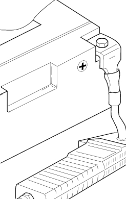
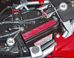
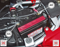
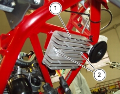
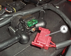
The 30A fuse placed on tank protects the electronic regulator. To gain access to the fuse, it is first necessary to remove the seat (Sect. E 3, Removing the seat) and remove solenoid starter connector (A).
You can tell a blown fuse by the broken filament (B).
Caution
To prevent short circuits, ensure that the ignition key is in the OFF position before changing a fuse.
Warning
Use only fuses with the specified amperage. Using fuses with the incorrect amperage may damage the electrical system and cause fires.