3 -
Electronic control unit
Engine ECU (1) is an electronic digital microprocessor-based unit.
It controls both injectors and coils, thus controlling injection and ignition depending on engine operating conditions as detected by the following sensors.
-
-
-
-
-
Moreover, the engine control unit monitors battery voltage to adjust injector opening time and ignition coil charging time.
The electronic control unit determines the following values.
-
-
-
Caution
Mapping including ignition advance values, injection times, crankshaft angle for injector closing and all correction curves as a function of temperature and atmospheric pressure values are stored into the ECU Flash Eprom. The above values are preset by the Manufacturer after testing the motorcycle under different riding conditions.
Settings cannot be changed.
 
CO content can be adjusted via software through the "DDS", which should be connected to the ECU diagnosis outlet.
Please refer to Sect. D 5, Adjusting idling condition.
Warning
If the control unit was replaced, perform a “Zero setting the throttle position sensor (TPS)” (Sect. D 5).
Removing the electronic control unit
To remove the electronic control unit it is necessary to remove the right fairing (Sect. E 2, Removing the side fairings), disconnect the two connectors (1) and (2) from control unit.
Unscrew and remove the retaining screws (3) and remove the ground cable (4) from the front screw.
Remove the control unit from the vehicle.
Refitting the electronic control unit
Fasten the control unit to control unit mount starting the two screws (3) into their thread.
Insert the ground cable (4) at the lower screw (3), as shown.
Tighten the screws (3) to the specified torque (Sect. C 3, Frame torque settings).
Warning
The control unit is in the correct position when the lugs (A) are pointing to the control unit mount.
The connector (1) has a grey pinout (frame end -Body), whereas the connector (2) has a black pinout (engine end -Engine).
Make sure the clip (B) for connector (1) is “released” (as shown in the diagram).
Push the connector axially fully home into the control unit.
Rotate the clip (B) until locking the connector (clip is in the “locked” position).
Repeat procedure for the other connector (2).
Electric injector
Injectors (1) deliver the right amount of fuel for trouble-free engine operation.
The injector is made up of a body (2) and a needle (3) which is connected to the armature (4). The needle is pressed against the seat by a helical spring (5), whose loading is determined by an adjustable pushrod (6). The winding (7) is accommodated inside the injector body at the rear end, whereas the injector nose (8) at the front end incorporates needle seat and guide.
The ECU controls power supply to a winding (7), which creates a magnetic field attracting an armature (4) and causing fuel injection. Assuming that fuel properties such as viscosity and density as well as injector delivery and pressure head -which is controlled by pressure regulator- do not change over time, the amount of injected fuel depends on injector opening time. This time is set by the control unit according to engine operating conditions, for correct fuel feeding.
See Sect. L 6, Removing the injectorsRefitting the injectors, for injector removal and installation instructions.
Note
To check operation of the injector, use the DDS, please refer to "Guided diagnosis" (Sect. D 5).
 
The outfeed of the fuel must be steady and the jet must be atomised, without drops.
Do not leave the fuel system filled with fuel if you are leaving the motorcycle unused for long periods. The fuel could clog and damage the injectors. If the engine has been idle for long periods, add a special additive “TUNAP 231” to the tank at regular intervals. This cleans the critical fuel passages.
Stepper motor
The throttle body incorporates an automatic cold start function that is carried out by a stepper motor (1).
The stepper motor shaft is equipped with a shutter that moves and puts two holes -one (2) connected to vertical cylinder intake manifold and the other one (4) connected to horizontal cylinder intake manifold- in connection with a third hole (3) connected to the airbox.
The stepper motor controls at the same time two by-pass holes having an air capacity of about 6 Kg/h.
The by-pass holes fitted with the manual adjusters are still available since they are necessary for balancing the cylinder air flows.
The engine control system “converts” stepper motor steps in degrees for throttle angle so that opening the stepper motor is like opening the throttle. This allows for compensation for the additional air supplied through the stepper motor and hence for ensuring that the correct quantity of fuel is supplied.
Note
The air going through the stepper motor affects injection up to 30° of throttle opening; no correction is necessary above this value.
 
The strategies controlling stepper opening are 2:
Strategy 1) exclusively controlled by engine temperature (stepper motor opening or closing is only determined by engine temperature).
Strategy 2) controlled by engine temperature and engine status. This strategy is only active during starting; the system determines a quantity of steps, to be added to the ones of the previously indicated strategy, that are immediately decreased until zero as soon as the system detects that engine has started, according to number of engine cycles.
 
Lambda sensor
The lambda sensor (1), located on the exhaust pipe, is the sensor giving the control unit information about the quantity of oxygen in the exhaust gases. This helps the electronic control unit in maintaining optimum air-fuel ratio.
The outer surface of the zirconium dioxide element is exposed to the exhaust gas, whereas the inside is vented to the atmosphere. Both the inner and outer surfaces are coated with a thin layer of platinum. Oxygen ions flowing through the ceramic electrically charge the platinum layer, which acts as an electrode and produces a measurable voltage; this voltage is delivered to sensor output and on to the connection cable attached to it.
The zirconium dioxide element becomes permeable to oxygen ions when heated up to about 300 °C.
The sensor uses the special physical properties of zirconium dioxide to generate a voltage relating to the difference in oxygen content of the gases on either side of the element. A lean mixture produces a low voltage signal, whereas a rich mixture will result in a high voltage output.
The sensor is set to change its output at an air/fuel ratio of 14.7:1 (14.7 parts of air to 1 part of fuel) known as Lambda 1. This is considered as the ideal ratio for complete combustion, hence the name Lambda Sensor: therefore
lambda = 1 means stoichiometric mixture ratio
lambda >1 means lean mixture
lambda <1 means rich mixture
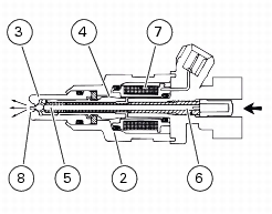
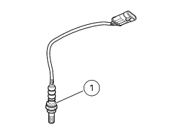
The air/fuel mixture control system varies mixture content based on the information provided by the sensor, which starts operating above 300°C: the ceramic core becomes permeable to oxygen ions when heated up to about 300°C. Due to the particular characteristics of the material, the difference in oxygen content on either side of the sensor generates a voltage across the two electrodes. And this allows measuring the difference in oxygen content of exhaust gases and the environment. When the air/fuel mixture sent to the combustion chamber is not correct, gases produced after engine combustion still feature a residual oxygen content. This system then controls the fuel injection electronic control unit so that engine always uses ideal mixture.
Throttle position sensor
This sensor is powered by the electronic unit to which it sends a signal that identifies the position of the throttle. This information is the indirect measure for engine load and is used by the control unit as a main parameter for calculating the dose of fuel and the ignition advance.
To check operation of this item, use the DDS, please refer to "Guided diagnosis" (Sect. D 5).
The throttle position sensor cannot be replaced alone. Should some malfunctioning arise, change the throttle body (Sect. L 6, Removing the throttle body) and then compulsorily reset the throttle position sensor [Sect. D 5, Zero setting the throttle position sensor (TPS)].
Rpm/timing sensor
This is an inductive sensor. The engine sensor is facing the timing gear and can read the 46 teeth and the gap equal in size to 2 teeth.
The signal output by the pick-up sensor is used by the ECU to read the engine rpm and as a timing reference.
Note
To check operation of these items, use the DDS, please refer to "Guided diagnosis" (Sect. D 5).
 
See Section “Flywheel - generator” (Sect. N 8) for instructions on how to replace the sensor and check the air gap.
Air temperature / pressure sensor
This sensor is powered by the electronic unit. It supplies information about the absolute air pressure in a neutral area of the motorbike and measures temperature. The sensor sends electronic signals to the control unit for correction in accordance with the temperature and barometric pressure.
Note
To check operation of this component, use the DDS, follow instructions given under "Guided diagnosis" (Sect. D 5).
Removing the air temperature / pressure sensor
To gain access to the air temperature/pressure sensor, remove the headlight fairing (Sect. E 1, Removing the headlight fairing), disconnect the main wiring harness connector (1) at sensor end, unscrew the sensor retaining screw (2) and remove the sensor from the front subframe.
Refitting the air temperature / pressure sensor
Reverse the removal procedure and tighten the sensor retaining screw (2) to the specified torque (Sect. C 3, Frame torque settings).
After refitting, reconnect the connector (1) to the sensor.
Refit the headlight fairing (Sect. E 1, Refitting the headlight fairing).
Spark plugs
Blow spark plug recesses with compressed air to remove any dirt.
Remove each spark plug cap (1) from the four spark plugs and unscrew the spark plugs from both cylinder heads. Make sure that no dirt or other objects can fall into the combustion chamber.
 
Caution
Check gap between centre and side electrodes.
Replace the spark plug if taken value is different from the specified one or the spark plug shows clear signs of carbon settling.
Screw the spark plug in by hand until the full thread is into the head.
Tighten to the specified torque (Sect. C 3, Engine torque settings).
Refit spark plug caps (1).
Caution
Do not use spark plugs with an unsuitable heat rating or incorrect thread length. Spark plugs must be properly tightened. Spark plugs that are not correctly tightened will overheat and may cause engine damage.
 
Make:
NGK
Type:
DCPR8E
As an alternative:
Make:
CHAMPION
Type:
RA6 HC
Coil
Ignition uses the inductive discharge technique. The power coil is governed by the I.A.W. control unit that calculates the ignition advance. The power module (built into the electronic control unit) also guarantees constant coil charge, operating on the dwell angle.
The horizontal cylinder coil (1) and the vertical cylinder coil (2) are fastened onto the airbox.
Remove the airbox (Sect. L 7, Removing the airbox) to gain access to the coils.
Unscrew the retaining screws (3) and remove the spacer (4) from the coil (1).
During reassembly, tighten the retaining screws (3) to the specified torque (Sect. C 3, Frame torque settings).
If disconnected from coils, connect spark plug cables (5), (6), (7) and (8) as shown. Horizontal and vertical coils have a different spark plug cable (different length): vertical coil (1) has shorter spark plug cables (5) and (6), while horizontal coil (2) has longer spark plug cables (7) and (8).
Refit the air box (Sect. L 7, Refitting the airbox).
Please refer to the following diagrams for the correct routing of coil cables.
Note
To check these components, use the “DDS” test equipment (Sect. D 5, Guided diagnosis).
 
Injection relay
The relay (1) is located on fuel tank.
Remove the seat (Sect. E 3, Removing the seat) to gain access to the relay.
Disconnect the relay from the electric system and power contacts (86) and (85) (small contacts) with 12 V (battery). The electric magnet must click.
Connect the multimeter to contacts (30) and (87) (large contacts) to check for electric continuity (Section P 9, "Test equipment" on multimeter operation). Resistance value taken by the multimeter should be close to zero and, if available, a continuity beep should be heard. If not, replace checked part.
 
CAN line
This model uses the CAN line (Controller Area Network) that considerably simplifies the electric system layout and thus even its overall volume.
Two units are connected to CAN:
the instrument panel and engine control unit (I.A.W. 5AM2).
Thanks to this communication line no sensor doubles are required as sensor signals are shared by both electronic units. Sensors are connected to closer electronic unit (instrument panel or engine control unit), which sends the signals to the network to be processed by the control units.
CAN line consists of two wires for digital signal transfer; they both carry precise and perfectly decipherable data. The instrument panel and the engine control unit, which are connected to the CAN line, are fitted with special hardware which acknowledges whether a pulse sequence includes pertaining data to be processed by the computing unit.
Signals exchanged between instrument panel and engine control unit via CAN line are the following:
-
-
-
-
-
-
-
-
-
-
-
-
-
-