3 -
Electronic control unit
Engine ECU (1) is an electronic digital microprocessor-based unit.
It controls both injectors and coils, thus controlling injection and ignition depending on engine operating conditions as detected by the following sensors.
-
-
-
-
-
Moreover, the engine control unit monitors battery voltage to adjust injector opening time and ignition coil charging time.
The electronic control unit determines the following values.
-
-
-
Caution
Mapping including ignition advance values, injection times, crankshaft angle for injector closing and all correction curves as a function of temperature and atmospheric pressure values are stored into the ECU Flash Eprom. The above values are preset by the Manufacturer after testing the motorcycle under different riding conditions.
Settings cannot be changed.
Removing the electronic control unit
To remove the control unit, remove the fuel tank (Sect. L 2, Removing the fuel tank), disconnect the two control unit connectors (1) and (2), unscrew the retaining screws (3) and detach the control unit ground cable (4) from the screw (3).
Unscrew the other screw (3) and remove the control unit.
Refitting the electronic control unit
Position the control unit to the battery mount (5) (on the right side of the motorcycle) and start the two screws (3) in their holes.
Place the ground cable (4) under the rear screw as shown in the figure.
Warning
The control unit is in the correct position when the lugs (A) are pointing to the right (viewing the motorcycle from rider position).
 
Tighten the screws to the specified torque (Sect. C 3, Engine torque settings).
The connector (1) has a grey pinout (frame end -Body), whereas the connector (2) has a black pinout (engine end -Engine).
Caution
If the control unit is replaced, it is necessary to use the DDS and carry out the procedure for Zero setting the throttle position sensor (TPS) (Sect. D 5).
 
Make sure the clip (B) for connector (1) is “released” (as shown in the diagram).
Push the connector axially fully home into the control unit.
Rotate the clip (B) until locking the connector (clip is in the “locked” position).
Repeat procedure for the other connector (2).
Make sure the connector clip is “released”.
Push the connector axially fully home into the control unit.
Rotate the clip until locking the connector (clip is in the “locked” position).
Electric injector
Injectors (1) deliver the right amount of fuel for trouble-free engine operation.
The ECU controls power supply to a winding, which creates a magnetic field attracting an armature and causing fuel injection. Assuming that fuel properties such as viscosity and density as well as injector delivery and pressure head -which is controlled by fuel pressure regulator- do not change over time, the amount of injected fuel depends on injector opening time. This time is set by the control unit according to engine operating conditions, for correct engine feeding.
The injector is made up of a body (2) and a needle (3) which is connected to the armature (4). The needle is pressed against the seat by a helical spring (5), whose loading is determined by an adjustable pushrod (6). The winding (7) is accommodated inside the injector body at the rear end, whereas the injector nose (8) at the front end incorporates needle seat and guide.
See Section L 6 for injector removal and installation instructions.
Note
To check operation of the injector, use the DDS, please refer to "Guided diagnosis" (Sect. D 5).
 
The outfeed of the fuel must be steady and the jet must be atomised, without drops.
Do not leave the fuel system filled with fuel if you are leaving the motorcycle unused for long periods. The fuel could clog and damage the injectors. If the engine has been idle for long periods, add a special additive “TUNAP 231” to the tank at regular intervals. This cleans the critical fuel passages.
Lambda sensor
The lambda sensor (1), located on the exhaust pipe, is the sensor giving the control unit information about the quantity of oxygen in the exhaust gases. This helps the electronic control unit in maintaining optimum air-fuel ratio.
The outer surface of the zirconium dioxide element is exposed to the exhaust gas, whereas the inside is vented to the atmosphere. Both the inner and outer surfaces are coated with a thin layer of platinum. Oxygen ions flowing through the ceramic electrically charge the platinum layer, which acts as an electrode and produces a measurable voltage; this voltage is delivered to sensor output and on to the connection cable attached to it.
The zirconium dioxide element becomes permeable to oxygen ions when heated up to about 300 °C.
The sensor uses the special physical properties of zirconium dioxide to generate a voltage relating to the difference in oxygen content of the gases on either side of the element. A lean mixture produces a low voltage signal, whereas a rich mixture will result in a high voltage output.
The sensor is set to change its output at an air/fuel ratio of 14.7:1 (14.7 parts of air to 1 part of fuel) known as Lambda 1. This is considered as the ideal ratio for complete combustion, hence the name Lambda Sensor: therefore
lambda = 1 means stoichiometric mixture ratio
lambda >1 means lean mixture
lambda <1 means rich mixture
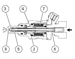
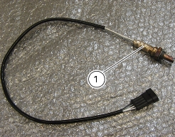
The air/fuel mixture control system varies mixture content based on the information provided by the sensor, which starts operating above 300°C: the ceramic core becomes permeable to oxygen ions when heated up to about 300°C. Due to the particular characteristics of the material, the difference in oxygen content on either side of the sensor generates a voltage across the two electrodes. And this allows measuring the difference in oxygen content of exhaust gases and the environment. When the air/fuel mixture sent to the combustion chamber is not correct, gases produced after engine combustion still feature a residual oxygen content. This system then controls the fuel injection electronic control unit so that engine always uses ideal mixture.
Unscrew the lambda sensor (1) from the exhaust pipe to remove it.
To refit, tighten the sensor to the specified torque (Sect. C 3, Frame torque settings).
Air temperature / pressure sensor
This sensor is powered by the electronic unit. It supplies information about the absolute air pressure in a neutral area of the motorbike and measures temperature. The sensor sends electronic signals to the control unit for correction in accordance with the temperature and barometric pressure.
Note
To check operation of this component, use the DDS, follow instructions given under "Guided diagnosis" (Sect. D 5).
Removing the air temperature / pressure sensor
To gain access to the air temperature/pressure sensor (1), remove the headlight (Sect. P 4, Changing the headlight), disconnect the main wiring harness connector (3) at sensor end, unscrew the sensor retaining screw (2) and release the screw from the front subframe.
Refitting the air temperature / pressure sensor
Reverse the removal procedure and tighten the sensor retaining screw (2) to the specified torque (Sect. C 3, Frame torque settings).
After refitting, reconnect the connector (3) to the sensor.
Refit the headlight (Sect. P 4, Changing the headlight).
 
Spark plugs
Blow spark plug recesses with compressed air to remove any dirt.
Take out spark plug caps (1) on both heads and remove spark plugs. Take care not to let any foreign body enter the combustion chambers.
Caution
Check gap between centre and side electrodes.
If gap is outside the specified limits or in case of carbon deposits on spark plug surface, change spark plug.
Screw the spark plug in by hand until the full thread is into the head.
Tighten it to the specified torque (Sect. C 3, Frame torque settings).
Refit spark plug caps (1).
Caution
Do not use spark plugs with an unsuitable heat rating or incorrect thread length. Spark plugs must be properly tightened. Spark plugs that are not correctly tightened will overheat and may cause engine damage.
 
Spark plug type
Make: NGK
Type: DCPR8E
Make: Champion
Type: RG4HC
Coil
Ignition uses the inductive discharge technique. The power coil is governed by the I.A.W. control unit that calculates the ignition advance. The power module (built into the electronic control unit) also guarantees constant coil charge, operating on the dwell angle.
Horizontal head coil (1) is placed under the airbox. Remove the airbox (Sect L 7, Removing the airbox) to gain access to the coil.
Vertical head coil (2) is located next to the wheel, in the rear left side of the vehicle.
Disconnect spark plug cable (3) to remove the coil (1).
Undo the nuts (4) and collect the washers.
Remove the coil (1) from the plate (5).
Disconnect the spark plug cable (6) and remove screws (7) to remove the coil (2).
Remove the coil (2).
Installation is a reversal of the removal procedure. Be sure to tighten the nuts (4) and screws (7) to the specified torque (Sect. C 3, Frame torque settings).
Note
To check operation of these items, use the DDS, please refer to "Guided diagnosis" (Sect. D 5).
Throttle position sensor
This sensor is powered by the electronic unit to which it sends a signal that identifies the position of the throttle. This information is the indirect measure of the engine load and is used by the unit as a key parameter for calculating the quantity of fuel and the ignition advance.
Note
To check operation of this item, use the DDS, please refer to "Guided diagnosis" (Sect. D 5).
The throttle position sensor cannot be replaced alone. Should some malfunctioning arise, change the throttle body (Sect. L 6, Removing the throttle body) and then compulsorily reset the throttle position sensor (Sect. D 5, Zero setting the throttle position sensor (TPS)).
Rpm/timing sensor
This is an inductive sensor. This sensor is facing the timing gear and can read the 46 teeth and the gap equal in size to 2 teeth.
The signal from the pick-up sensor -facing the timing layshaft gear- is used by the control unit for calculating engine rotation speed and timing reference values.
Note
To check operation of these items, use the DDS, please refer to "Guided diagnosis" (Sect. D 5).
 
See Section “Flywheel - generator” (Sect. N 8) for instructions on how to replace the sensor and check the air gap.
Main and injection relays
Relay (1) is located next to the battery and is fixed to battery support.
To remove the relay, first lift the fuel tank (Sect. L 2, Removing the fuel tank).
Disconnect the relay from the electric system and power contacts (86) and (85) (small contacts) with 12 V (battery). The electric magnet must click.
Connect the multimeter to contacts (30) and (87) (large contacts) to check for electric continuity (Section P 9, Testers, on multimeter operation). Resistance value taken by the multimeter should be close to zero and, if available, a continuity beep should be heard. If not, replace checked part.