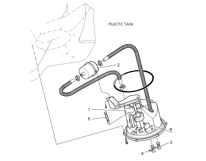
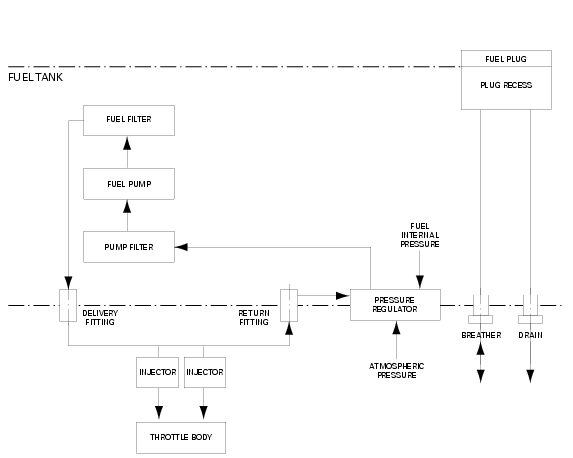
The fuel system takes the fuel to the electric injectors and controls its pressure. Electric injectors are suitably controlled by the control unit and spray the fuel that thus mixes with air taken in by the engine. Fuel capacity varies depending on the engine operating conditions. The fuel system consists of an electric pump immersed in the fuel tank that takes fuel in though a filter and puts it under pressure. The fuel goes through a second finer filter and is sent to fuel tank output fitting. From here the fuel reaches a "Tee" through an outer line from which two lines branch off: one line to the electric injectors which are fed in parallel and one line to the tank return fitting. The pressure regulator receives fuel from this last hose and keeps it at 3 bars in the whole fuel system. Regulator output fuel is not under pressure and is sent to the electric pump intake port, through a Venturi-type channel that makes it easier to take fuel from the tank bottom, even when the level is extremely low. Since the channel is built in the pump plastic support it is not possible to measure fuel capacity on pressure regulator output.