6 -
1
2
3
4
5
6
7
8
9
10
11
12
13
14
15
16
Spare parts catalogue
Caution
Bold reference numbers in this section identify parts shown in this exploded view diagram. These parts do not appear in the figures near the text.
Removing the rear brake system
 
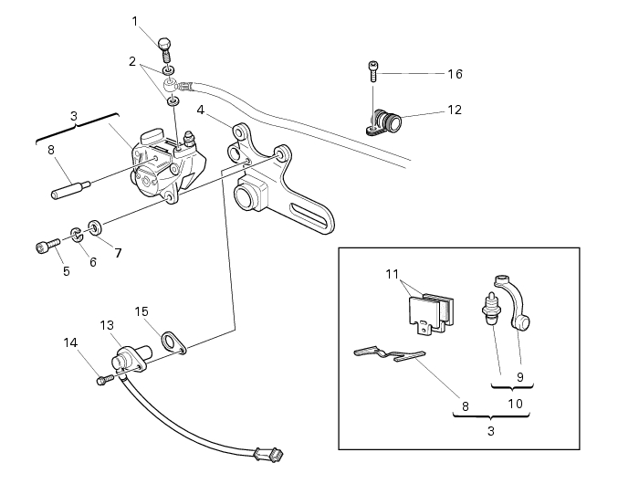
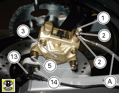
Remove the screw retaining the hose to the rear brake cylinder and the seals
Caution
Critical safety components. The brake caliper manufacturer recommends that you do not attempt to service the internal components of the brake caliper. Incorrect overhaul of these critical safety components can endanger rider safety.
 
Maintenance operations on these units are limited to replacing brake pads, fasteners and bleed unit.
Release and remove the special screw (1) retaining the hose (A) to the rear brake caliper and the seals (2).
Note
Take a rag at hand to dry any possible brake fluid spillage.
 
Unscrew the screw (16).
Remove the hose (A) together with the retainer (12).
Unscrew the two screws (5) that retain the rear brake caliper to the caliper mounting plate. Collect the spring washers (6) and the washers (7).
Remove the caliper (3).
Note
For brake pads replacement operations see section D 4, Checking brake pad wear. Changing brake pads.
 
To remove the speed sensor (13), unscrew the screw (14) retaining the sensor to the caliper mounting plate and collect the spacer (15).
Remove the rear wheel to remove the caliper plate (Sect. G 4, Removing the rear wheel).
Slide caliper plate out of swingarm shaft (P).
Refit the caliper mounting plate on the swingarm shaft.
Refit the rear wheel (Sect. G 4, Refitting the rear wheel).
Refitting the rear brake system
If you have removed the speed sensor (13), position it to the caliper holder plate with the spacer (15) and tighten the screw (14) to the specified torque (Sect. C 3, Frame torque settings). Fit the special copper gaskets (2) to the connector when securing the brake hose (A) to the brake caliper. Fit hose connector (A) to the caliper, and position it as shown.
Warning
Incorrectly positioned hoses can cause brake faults and interfere with moving parts.
 
Tighten the special screws (1) to the specified torque (Sect. C 3, Frame torque settings). Position the brake hose (A) to the swingarm and secure the retainer (12) with the screw (16).
Fit the rear brake caliper (3) to the brake disc matching the holes in the caliper plate. Grease the thread and underhead of the screws (5). Slide the washers (7) and the spring washers (6) on the screws (5). Tighten the screws (5) to the specified torque (Sect. C 3, Frame torque settings).
 
Note
The air gap between sensor (13) and brake disc retaining screw (14) must be 0.6-2.2 mm.
 
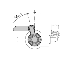
Tighten the screw retaining the hose to the rear brake master cylinder