|
2
|
|
6
|
|
8
|
|
9
|
|
13
|
|
14
|
|
19
|
|
20
|
|
21
|
|
22
|
|
24
|
|
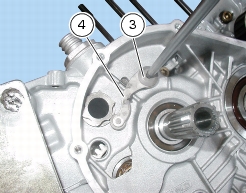
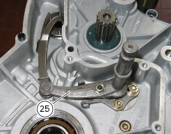
Remove generator cover and flywheel/generator assembly
|
|


|
Refit flywheel/generator assembly and generator cover
|