|
1
|
|
2
|
|
5
|
|
9
|
|
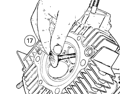
17
|
|
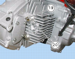
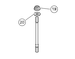
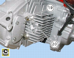
19
|
|
20
|
|
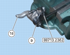
Disconnect oil temperature sensor from main wiring harness
|
|


|
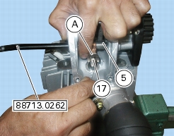
Connect oil temperature sensor to main wiring harness
|
|