
|
5 -
|

|
-
|
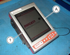
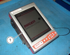
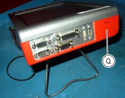
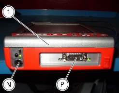
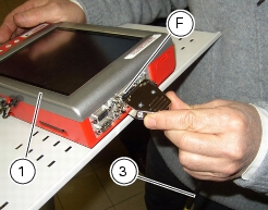
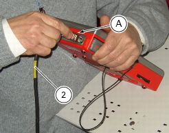
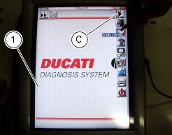
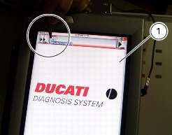
from the instrument own battery: the battery (Q) is located at the top of the instrument. Please refer to the "User's Manual" supplied with the DDS for instructions on how to use the instrument (1) with its battery and how to charge it.
|
|
-
|
|
-
|
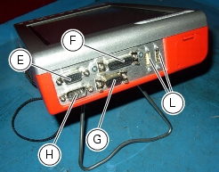
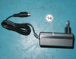
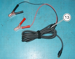
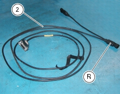
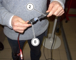
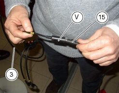
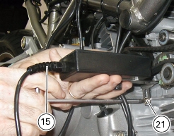
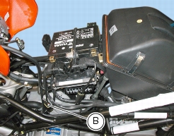
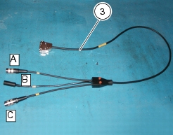
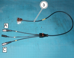
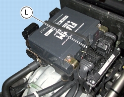
connecting the power and diagnosis cable (2) to instrument diagnosis connector (P); connecting battery adapter (8) to power and diagnosis cable connector (R) and then connecting the adapter to the vehicle battery.
|

|
-
|
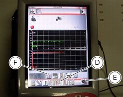
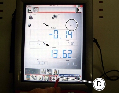
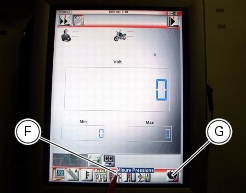
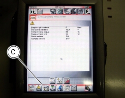
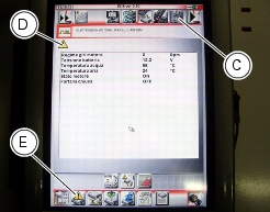
Parameter reading, such as engine rpm, coolant and air temperature, atmospheric pressure, throttle opening value, battery voltage, injection times, ignition advance values and so on.
|
|
-
|
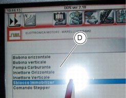
Active diagnosis. Enabling of ignition-injection system transducers to check for proper operation and correct control signal (fuel pump, ignition coils, rev counter, injectors and so on). This function also allows entering the safety code for bypassing the immobilizer system.
|
|
-
|
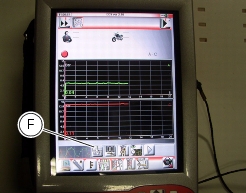
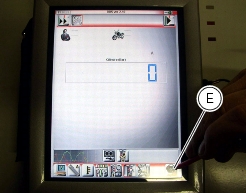
Road test. This function allows you to store engine parameters within a preset rpm range. At the end of their acquisition, these parameters are then analyzed and displayed.
|
|
-
|
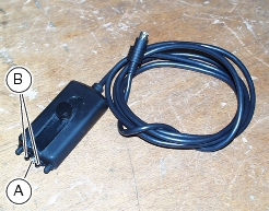
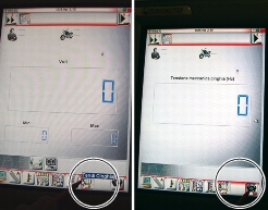
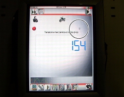
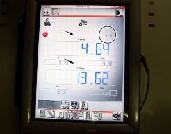
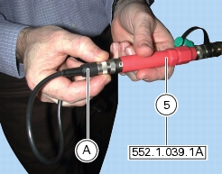
If connected to special feelers, the DDS can read voltage, current and temperature values as well as timing belt tension values and pressure values into oil and fuel circuits.
|


|
-
|


|
-
|
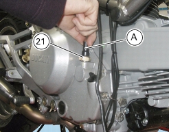
standard value: 11-12 bar;
|
|
-
|
minimum value: 10 bar;
|


|
|
|
|
|
|
|
|
|
|
|
|
|
|
|
|
|
|
|
|
|
|
|
|
|
|
|
|
|
|
|
|
|
|
|
|
|
|
|
|
|
|
|
|
|
|
|
|
|
|
|
|
|
|
|
|
|
|
|
|
|
|