5 -
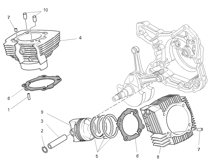
Cylinder / piston assy
1
Pin
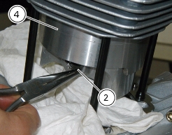
2
Circlip
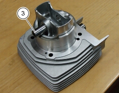
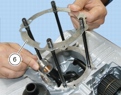
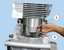
3
Gudgeon pin
4
Vertical cylinder
5
Piston rings
6
Cylinder base gasket
7
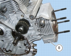
Pin
8
Horizontal cylinder
9
Piston
10
Centering bush
Parts catalogue
1100
Cylinders - pistons
1100S
Cylinders - pistons
Caution
Bold reference numbers in this section identify parts shown in this exploded view diagram. These parts do not appear in the
figures near the text.
Removing cylinder / piston assy
Operations
Reference - See Section
Remove the heads
N 4.4,
Disassembling the engine heads
Remove the pin (7), the bushes (10) and the head gasket (A) from their seats into the cylinder (Section N 4.4,
Disassembling the engine heads
).
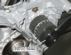
Use tool part no.
88700.5644
to bring horizontal cylinder piston (8) to TDC.
Extract the cylinder (4). Keep it square and pull gently.
If needed, aid removal by rocking the cylinder gently with both hands or tap cylinder base lightly with a plastic mallet. Lift cylinder
just enough to give access to gudgeon pin (3).
Cylinder and piston are best removed together. This will save time on reassembly, as inserting the piston into the cylinder is a
delicate, lengthy procedure. The recommended removal procedure is as follows.
Block off the casing opening with a cloth or with soft paper to prevent foreign matters or solid waste from entering the engine
block.
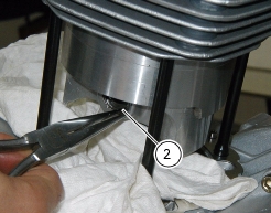
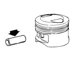
Remove the gudgeon pin (3) circlip (2) on clutch side.
Working from the opposite side, withdraw gudgeon pin (3) just enough to release the connecting rod.
Lift the piston-cylinder assembly clear of the stud bolts.
If you need to service the piston, lift gently until clear of the cylinder.
Remove the gaskets (6) placed between cylinder and casing.
Caution
Mark the pistons with their positions so as to refit each piston to the matching cylinder on reassembly:
V= Vertical - O= Horizontal
Bring the horizontal cylinder piston (8) to top dead center using tool part no.
88700.5644
. Repeat operations performed on the vertical cylinder to remove horizontal cylinder-piston assembly.
Overhauling the cylinder / piston assy
Overhauling the cylinder
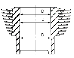
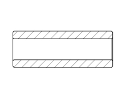
Check that the inner surface is perfectly smooth. Measure the cylinder bore diameter (D) at three different heights and in two
directions at 90° to one another. This makes it possible to obtain the coupling, taper and oval values (see specified values under Sect. C 1.1,
Cylinder / piston
).
Change the cylinder if damaged or excessively worn. The special silicon carbide coating applied to the inner bore provides
excellent friction and wear resistance, but prevents grinding.
The cylinders are marked with their class (a letter punched on the side of the cylinder).
Always match cylinder and piston from the same class.
Overhauling the piston
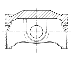
Clean the crown of the piston and the piston ring grooves from carbon deposits.
Inspect the dimensions of the piston carefully: there must be no signs of shrinkage, scoring, cracks or damage.
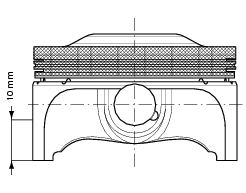
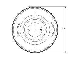
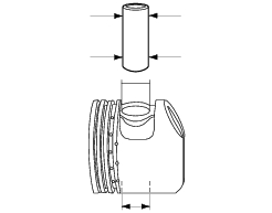
Measure piston diameter (P)
10
mm above skirt base, at right angles to the axis of the gudgeon pin.
Pistons must always be changed in pairs.
Piston-cylinder clearance
Pistons are marked with their class (a letter printed on the piston crown).
Always match cylinder and piston from the same class.
For clearance values refer to Sect. C 1.1,
Cylinder / piston
.
Overhauling the gudgeon pins
They must be perfectly smooth, without signs of scoring, steps or blueish stains due to overheating. The well-lubricated gudgeon
pin must slide smoothly inside the piston.
Assembly clearance must be:
0.002-0.008
mm
Max allowed wear limit:
0.035
mm
If you change the gudgeon pin, you must also change the connecting rod small end bush.
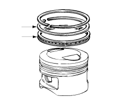
Overhauling the piston rings
The piston rings must not show any signs of forcing or scoring. Spare pistons are supplied with piston rings and gudgeon pin.
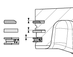
Piston ring-piston groove clearance
Top (1
st
) ring max. wear limit:
0.15
mm
Other rings (2nd ring and scraper ring) wear limit: 0.10 mm
Note
The mark punched on piston rings must always be facing up.
Gudgeon pin-piston clearance
Measure the diameter of the piston hole that accommodates the gudgeon pin.
Measure gudgeon pin diameter.
Wear limit:
0.025
mm.
Note
If you change the gudgeon pin, you must also change the connecting rod small end bush.
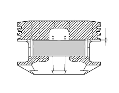
Piston rings-cylinder clearance
It is important that piston ring (A) be perfectly square to cylinder during measurement. To this end, fit the piston (9) without the
piston rings into the cylinder and place the piston ring to be measured on top of the piston.
Measure the piston ring end gap:
Top ring and second ring (nominal):
0.20 - 0.40
mm
Wear limit:
0.80
mm.
Oil scraper ring (nominal):
0.30
-
0.60
mm
Wear limit:
1.0
mm.
Refitting cylinder / piston assy
If you are using new cylinders and pistons, match cylinders and pistons from the same class.
Cylinder class is identified by a letter punched on cylinder top face in the cylinder / head contact surface. Piston class is punched
on the piston crown, between the two valve pockets.
If piston and cylinder were separated during disassembly, rotate piston rings so that their open ends are spaced 120 degrees
apart. Note that piston ring mark must be facing up (pointing to piston crown).
Lubricate cylinder inner bore with engine oil. Use an all-purpose tool to slide piston gently into cylinder with the smaller valve
pocket placed at exhaust end.
Clean off any carbon deposits and degrease the mating surfaces of engine casings and cylinders.
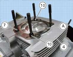
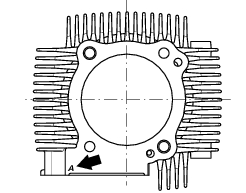
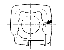
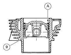
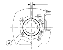
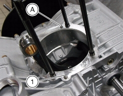
Ensure that the engine block includes the pin (1) allowing oil flow to the head and the cylinder centering pin (A).
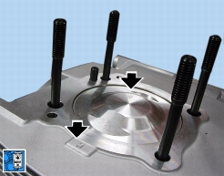
Apply liquid gasket to the gasket (6) mating surface as shown in the figure.
When fitting the gasket (6) onto the casing, "TOP" should be face up.
Use tool part no.
88700.5644
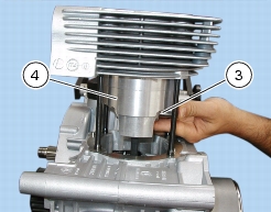
to bring connecting rod small end to TDC. Slide the cylinder-piston assembly onto the casing stud bolts.
Push connecting rod small end into the piston so as to line up gudgeon pin (3) hole. Lubricate and fit gudgeon pin. Gudgeon pin
must slide smoothly inside the con-rod small end bushing and piston (9).
Block off casing opening with a cloth, then fit circlip (2).
Caution
At reassembly, always use new circlips (2).
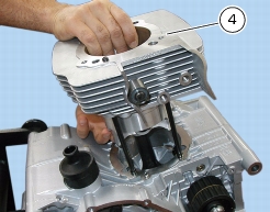
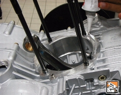
Press cylinder (4) down until it contacts the casing.
Apply liquid gasket onto the gasket (6).
Caution
Position the locating pin (
7)
, the head gasket (A) (Sect. N 4.4,
Refitting the heads
) and the centering bush (10).
Perform same operations to the other cylinder.
Operations
Reference - See Section
Refit heads on the engine
N 4.4,
Refitting the heads
1