|
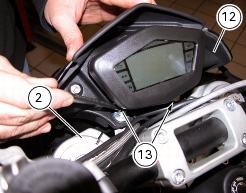
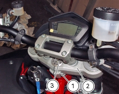
2 -
|
|
1
|
|
3
|
|
4
|
|
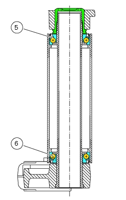
5
|
|
6
|
|
7
|
|
8
|
|
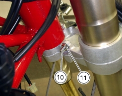
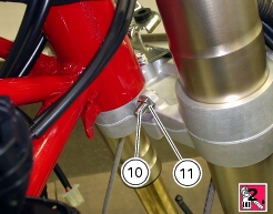
10
|
|
11
|
|
13
|
|
14
|
|
15
|
|
16
|
|
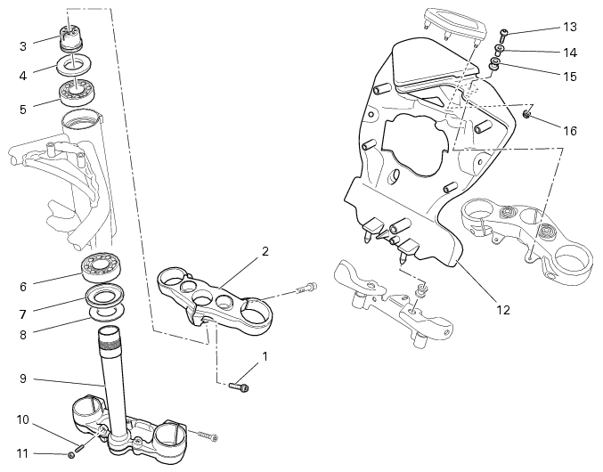
G 2, Removing the front fork (1100S)
G 2, Removing the front fork (1100)
|

|
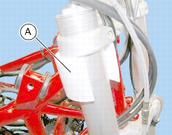
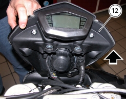
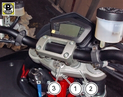
Connect the instrument panel to main wiring harness
|
|